Showing posts with label 3D Work. Show all posts

Wednesday, 11 June 2014

Take One Painting: Intro & CG

The first module of my "Digital Effects" course is called Take One Painting. This is a project that is used to teach us the basics of CG, Compositing, (via set extension) and working on set (placing tracking markers, VFX photography, set measurements, data wrangling). It also gave us the opportunity to work with the cinematography and production design courses.

The Brief

This is the entire plot behind the Take One Painting brief:

--> The heads of department choose a period painting

--> The production designers get shown the painting and are told to design a set based on the painting.

--> All 8 production designers design the set, and the best one is chosen to be used for the shoot.

--> The production designers then build the set and source the costumes.

--> The cinematographers come along, once the set is built, setup the camera in the same POV as that of the painter. They also setup and light the green screen.

--> We come when everything is ready perform all the necessary measurements, place all the tracking markers, record all the camera data, and take all necessary VFX photography.

--> Once the shoot is complete, we spend the next 6 months being taught Maya, Nuke, PFTrack and 

earning any other relevant software which will help in achieving a photorealistic set extension.
In this post I wish to take you through the same journey that I went through while learning about the entire port production pipeline. I am not going to go into very much detail regarding what I learn but I will be treating this as a progress report, and going over any major problems I faced.

The chosen painting this year was Hospital at Granada by John Singer Sargent, shown below:


Directly below are 2 stills from the tracking shot that was filmed:


We were also told to work on a locked off shot of the set, which was supposed to closely match the painting (with some added actions from the actors). Below is the still plate that I used, as well as the end result:


Tracking


All my tracking was done in PFTrack. I made a few tests in MatchMover before hand but went with something that is used professionally to get my final track.

The problem that I had with this footage was establishing a good camera solve. The reason for this problem was because I knew that the camera lens was set to 25mm, but I did not know what the EXACT focal length was. We did shoot a checkerboard grid with the same lens, however the actual lens grid was warped and old so using it would have actually introduced more errors.

I had no access to 3D equalizer for this project so I was not able to use its ability to detect the focal length of the camera. Instead what I did (shown in the image below), is that I manually entered different focal lengths (from 25.00mm to 26.7mm) and used the one that gave me the best result. The Estimate Focal node was not a very accurate way of estimating the focal length as it is all done by eye (exactly like the Orient Scene node below) which I find to be a pretty stupid idea.


Below are 2 images showing what my camera solve looked like using a focal length of 25mm and then 25.6mm. The left most group of points is supposed to represent the back wall of the set. In the 25mm solve these points are almost randomly scattered. While the 25.6mm gave me a pretty solid back wall (it is quite hard to see in the image actually).

25mm

25.6mm


Modelling and Texturing

I don't have many images for this stage because the CG is simply too far away to require any kind of really detailed, close-up friendly textures. Also (as you can see) the models are fairly low res as there would simply be too many things in front of them (the actors on stage, the banisters that connect the pillars etc.) for the detail to be seen.

A simple wheelchair I modeled to add into the background. Low poly and simple textures as it will only be seen temporarily, and it will be placed behind various other objects/actors.


Another simple prop I made. Once again, it was low poly and the textures were not super detailed. In the image of the chair 'cushion' you can see that the texture has various problems such as stretching and not being properly matched with the geometry. However none of this matters as the texture will look completely fine from far away (and the chair is, indeed, very far from the camera).


Below is a low poly detail that would be added between each of the columns. The two images directly below are there to show that my texturing was done using a combination of Photoshop and Mudbox and also CrazyBump for Normal maps.


Nothing in my scene was subdivided at render time. The arches are the only thing that has any real subdivisions and that is because of the way I wanted to model and texture each arch. In the image below, what you are seeing is extra edge loops added in in order to create more deformation. The scene might be geometric and straight, but it is man made, so nothing in it should ever be perfectly straight. The extra edge loops I added allowed me to add this extra level of deformation. This was done using the sculpt tool and in some cases, the selection tool with soft selection turned on.


As some of you may have noticed, based on the images above, I have used a combination of Maya and 3DS Max for the modelling of my scene. This led to a series of problems regarding imports and exports and file types. I will not go into too much detail but basically I needed to export my assets from Max to Maya, but I needed them to be instances. An OBJ file would not give me instanced versions of an object but it would maintain the correct scale. An OBJ would also sometimes place my exported item in the wrong place in my scene. An FBX file, on the other hand, would maintain instances, but in some cases it would also offset my models. Another problem that would occur is that my models would triangulate even though I had disabled triangulation. I found that for some reason I had to make sure I add an Edit Poly modifier to every object at the top of their modifier stack (in Max) and this would disable the triangulation upon import into Maya. The OBJ file would not have this problem, however, it had the other drawbacks that I mentioned.

Lighting

Below are screen captures of different lighting test results. After trying to match the shadow perspective and quality/hardness, I went back and forth from Maya to Nuke in order to compare the luminance values of my CG compared to the live action.
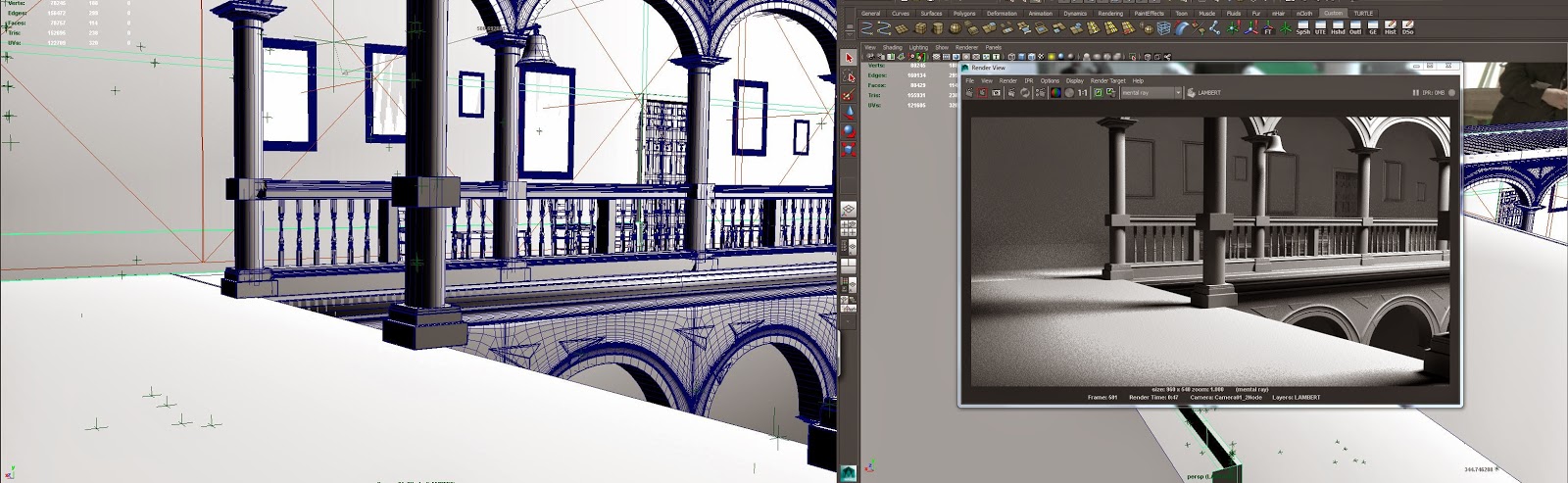


Trying to match the luminance difference between the shadowed areas and the ares fully exposed to the sun. I was sampling the actual footage in Nuke and then sampling the same light and shadow areas in the render.


Rendering

V-Ray was used for the rendering process. I had never used V-Ray before and thought that this would be a great opportunity to learn it. Below are all the render passes I rendered out. The multiple shadow passes were rendered out because I was having problems in the beginning with the default shadows pass. The Raw passes were also rendered out as a backup, in case I was having problems with their non-raw counterparts. One pass which I should have rendered is the Light Select, however I think that my multimatte passes, combined with my lighting and GI pass, might give me enough flexibility to not have to render out the Light Select. 


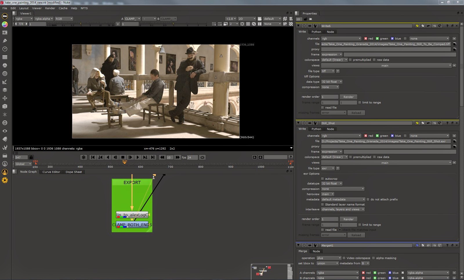
 Below is my Nuke script for my render passes. NOTE: this script was laid out before I actually knew about how to structure a script. So at the time, this made sense to me, however, now it doesn't so it will have to be re-organised.


Comparing my beauty pass with my comped render passes.


The CG roughly comped in with the live action.


Wednesday, 12 March 2014

Tires!

So, after about a month of Maya tuition, I am starting to update my blog again. In our tuition we have gone through modelling, unwrapping, texturing, shading, and we have started doing rigging. I have been working on some side projects which I haven't been to upload onto here but I will do so once I have permission.

For now, I have been working on tires for the Mitsubishi I modeled over the summer. Since I have been learning Maya, I decided to make the tire in Maya!

So, below, in the first image, I have modeled just one piece of the tire. This was modeled in the top down view and was based on the 4th design from the left, on the left screen. The key thing to remember is that the pattern HAS to be tile-able for later on. So, bearing that in mind, I selected the smallest piece of the pattern I needed to. To make life even easier for myself, I only modeled half of the tire as it is perfectly symmetrical on the left and the right.


The next stage is duplicating the piece I have modeled and making an approximate amount of copies which would then be made to revolve and make a wheel. This number is quite arbitrary and simply determines how many times you want the piece of the pattern to revolve (and create the final shape of the wheel).

The image below is the finished product with all vertices merged.


Below are a slightly different set of tires which I had made previously for the Mitsubishi. I chose a slightly simpler and 'bulkier' design to make them look more like off road tires.


After modelling the tire I decided that it needs some really nice alloys; and while I was at that, I decide it would be a good idea to challenge myself a bit (plus I wanted to model some really cool looking alloys).

Below you can see some progress images. I started off in Maya but I ran into problems when it came to constraining multiple edges all around the tire, so I continued the workflow in Max.


I have to be honest, half the reason I decided to do the alloy in Max is because Max is simply a much better 3D package when it comes to modelling (among other things).

Below is the finished result rendered out with a wireframe.

Wednesday, 1 January 2014

Matchmover

I have been meaning to learn this piece of sotware for a while now and I have finally got around to doing it. I have to say, this is possibly the easiest piece of software I have had to learn. For anyone interested in Matchmover it's a must for VFX. It's essentially a stand-alone 3D tracking software which tracks your footage and then sets 3D markers based on the track to calculate the 3D space. The easiest way to explain what Matchmover can do is by showing you. I was unable to upload my video onto blogger, so instead here is a link to the video on Vimeo:

https://vimeo.com/83174201

All I did was track the shot in matchmover, then I exported the tracking data as a 3D scene to 3DS Max and rendered everything together to composite it in After Effects. It is very simply stuff but I am quite happy with my first track.

Saturday, 28 September 2013

Perspective Match

This is somethign I have been very eager to try out. As I don't have 3DS Max 2014 I will have to model the environment (the hallway) and then use camera points (as opposed to simply using the perspective match function that comes with 2014).

So to start off with here is a photo of what I will be modeling:
Seeing as this is right outside my door, I was able to get up close to see the detail at any point during the modelling process.

All this had to be built to scale as it is necessary when adding the camera points. Below are some progress snapshots showing the progression of the modelling:


Building the walls first and making sure they are to scale. I was frequently going in and out of the room in order to get precise dimensions.


Building the door frames and cuttingout the holes for the doors from the wall (the image above was actually captured after the doors were made which is why the holes are there).


Working on the banister. The right one is smoothed using NURBS as it is easy to enable and disable the feature when I want to see how an object looks smoothed.


Working on some finer detail. This was done using a simple spline and then lathing.

First attempt at using the perspective match. The door frame is off quite a bit so below is the next attempt after adding a few more points.

Looking slightly better but still not perfect. I will keep working on the scene so I can take a video/photo from different parts of the hallway and have it modelled entirely.

Friday, 6 September 2013

Cupboard Modelling

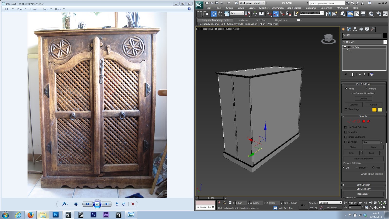
As I said I will make a new post for the modelling of the cupboard and post the progress as I go along. Here are some snapshots so far:


I just started by getting the scale and getting the basic shape right. Fortunately, it is basically just a box so this took the best part of 20 seconds.

Note that to begin with, I only had one monitor while working on this so I was a bit tight in terms of screen space.


Getting some of the relief patterns. Just a simple spline combined with a bevel profile to create the relief around the entire shape.


I now have 2 monitors! As you can see I was modelling the chain and the details around the doors. I also made the hinges work so the next bit will be modelling the mesh thing on the front of the doors.


Adding the handle was very easy. I just used a Geosphere and cut out the necessary polygons. Though I would need to retopolise it a little bit because there will be some issues in the corners when it is smoothed.


Creating the mesh itself was very simple and took almost no time at all. The planks which made up the mesh were not completely flat so I made sure to give them a slight surface curvature using soft selection and dragging out.
 

This is the first test render and I think it is coming along quite nicely. Obviously I still have more details to add but I realised I didn't have any renders or pictures of what the model looked like as a whole so I made this specifically for that reason.


This design was not the easiest to make due to the triangles present in the actual shape. On the left image you can see the way I developed the design bit by bit. I was actually copying the shape as I went along in case I messed up and wanted to go back. This would save me time as opposed to either using edit hold or saving each stage of the shape development as a different file. I am relatively happy with the end result although there are some very minor issues which are actually not noticeable even in a closer shot.


 Added a few extra details to the star thing and then added the actual circle around it. Oh and I also cut out the hole using ProBoolean to fit the shape in. I am fully aware of the huge drawbacks of using things like boolean and procutter but I'm not going to be smoothing that particular part and it is not going to deform so as long as that's the case then no need to worry too much about strange topology.


Looking much better now. I actually resized the whole thing because it was off and remade the mesh so that it is identical on all parts of both doors. Both doors are now rigged and open/close normally using a helper object. Just need to clean up a few very minor things, make sure everything is good for texturing, and start unwrapping!

 So that's the cupboard done! Now onto the texturing stage...

Here is a first glance at the beginning of the teturing process:


I actually made four variations of this texture, however it still seems very repetitive due to one thing that I failed to change (making it seem like it's the same pattern). This will be changed later on and updated on here.


I am much happier with this texture compared to the little triangle designs' texture. It looks much more natural and the size of the wood grain is perfect. This makes the individual triangle designs stand out as the texture might be a little bit high res and also the colour is a bit off. As I said, this will be changed later on once I can see it in context with everything else.


I am quite pleased with hos this has come out although I am a little unsure about the contact point between the big and small rings. I did not get a chance to take any close up photos of this for reference but I think I am heading in the right direction.


Here is another update to the cupboard. I have finished texturing the mesh of the door now and I have been working on the last few details. In the image above I have just done a quick test render to see if the mesh looks ok.


Above is the latest test render of the entire thing. It is looking pretty good although I have quite a few more adjustments to make. The two pattern circles are grey at the moment as I will be retexturing them. I'm also very unhappy with how the mesh has come out so that is something that I will have to go back to and refine.


Above is the finished render of the cupboard! I will begin matchmoving the video footage I have in order to start compositing this cupboard and show off my VFX skills!